The purpose of this exercise is to
- Construct a network residual model in MATLAB
- Solve network algebraic equations using MATLAB function fsolve
- Construct an DAE model of a network load in MATLAB
- Compute the time response using the implicit solver ode15i
STEP 1a
Download loadFlowOne.m, the residual function constructed in lecture and extend it to the full network. The first line of your function should be: [r,J] = dNetwork(x,s,z,p)
The network model is as follows:
S2 = n/conj(Z1)*conj(V0-n*V2)*V2 - conj(V2-V3)/conj(Z2)*V2;
S3 = conj(V2-V3)/conj(Z2)*V3;
The inputs are defined as follows: %x: network voltages; x = [V2R V2I V3R V3I]; %s: network injections; s = [-4 3]; %z: dynamic parameters; z = [1 1]; %p: static parameters; p = [X1 X2 Vm Vp nsT Qm Qp nsC];
The static parameters have the following values: X1 = 0.03; X2 = .05; Vm = .98; Vp = 1.02; Qm = -.25; Qp = .25; nsT = 0.025; nsC = .2;
The outputs are defined as follows: %r: residual; %J: Jacobian of the residual; J = dr/dx
STEP 1b
Compute the voltages V2 and V3 using the following command: Vn = fsolve(@(x)dNetwork(x,s,z,p),[V2R0 V2I0 V3R0 V3I0],optimoptions('fsolve','Jacobian','on','tolx',1e-12,'tolfun',1e-6,'display','off'));
Use the flat start for the initial voltage values, i.e., V2R0 = 1; V3R0 = 1; V2I0 = 0; V3I0 = 0;
The result should be: Vn = [0.9846 0.0300 0.9651 -0.1229];
STEP 2a
Download odefunBall.m, the residual function defining the DAE system for a pendulum. Use this as a template to construct a function for the network load. Notice, the model of the load your received in lecture included only 3 residues but the state below has five components. Hence you will need to add two fictitious residues for states 5 and 6. A common assumption is that the states not described in the module remain constant, in other words,
r(4) = d(4)
r(5) = d(5);
The first line of you function should be:
r = dLoad(t,x,d,z,p)
where % t = time % x: the continuous state vector; x = [xd Pd Qd V3R V3I]; %z: discrete state vector; z = []; %p: parameter vector; p = [Tp Ps Pt]; where Tp = 5; Ps = 3; Pt = .4;
STEP 2b
Compute the time response of the load using the ode15i solver. First you will need to call the function decic to compute the initial state:
[x0,d0] = decic(@(t,x,d)dLoad(t,x,d,z,p),t0,[xd0 Pd0 Qd0 V3R0 V3I0],[0 0 0 1 1],[0 0 0 0 0],[0 0 0 0 0]); where t0 = 0; xd0 = 2.6214; Pd0 = 3; Qd0 = 0; and the real and imaginary parts of voltage at node 3 are taken from Part1 of this exercise.
Next, compute the the response as follows:
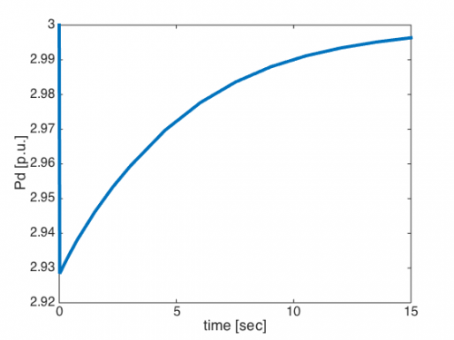
sol = ode15i(@(t,x,d)odefunBall(t,x,d,z,p),[0 15],x0p,d0); where d0 is taken from above and x0p is obtained from x0 as follows;
x0p = x0; x0p(4:5) = x0p(4:5)*.9;
This represents a 10% change in the voltage at node 3.
The time response should match the figure below:
